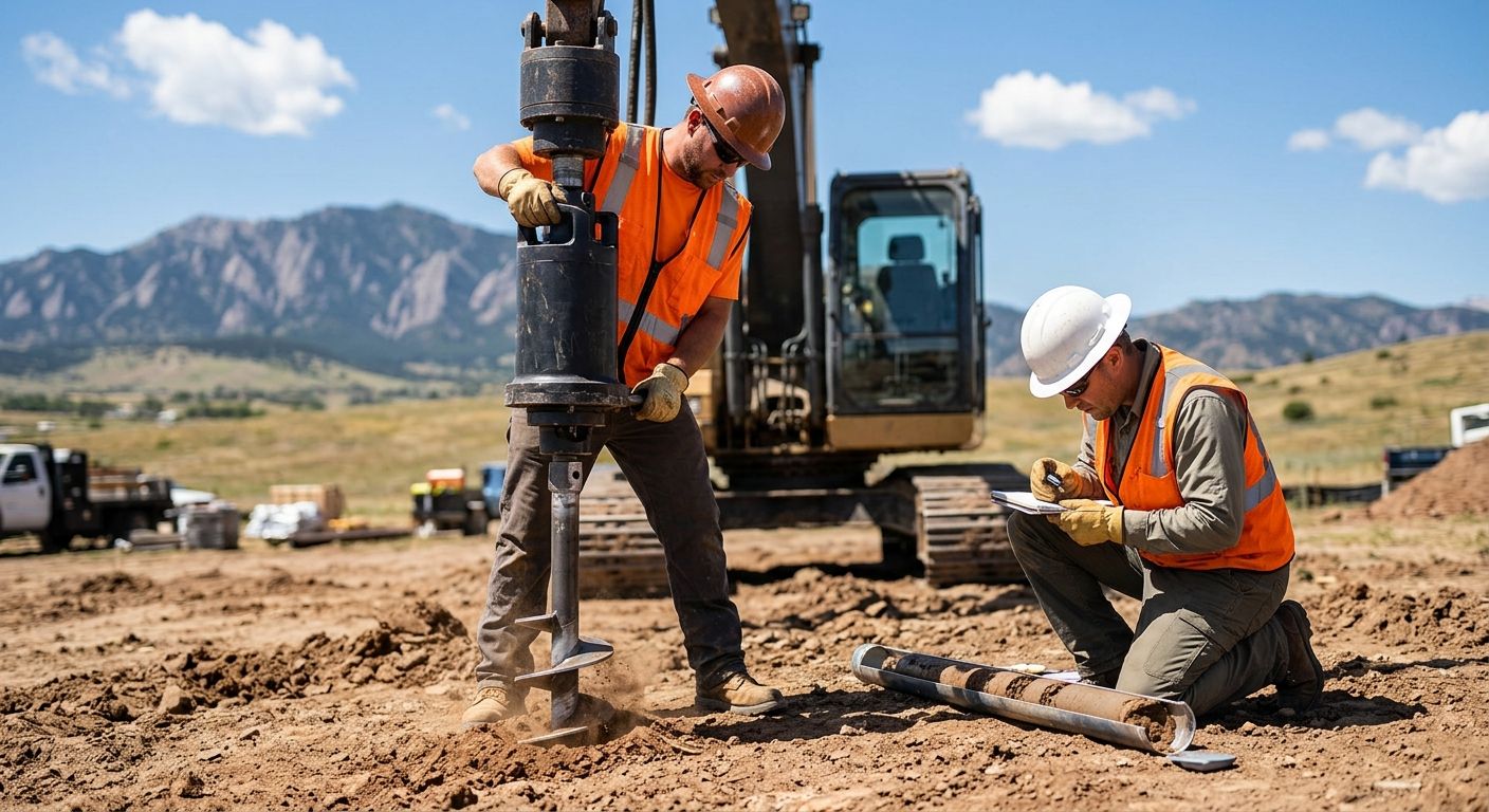
Soil Bearing Capacity for Helical Piers: A Guide for Centennial
Table of Contents
- Soil Bearing Capacity for Helical Piers in Centennial, Colorado
- Fundamentals of Soil Bearing Capacity for Helical Pier Foundations
- Deep Dive: Geotechnical Factors That Influence Helical Pier Bearing Capacity
- Practical Determination of Soil Bearing Capacity for Helical Pier Installation
- Advanced Analysis: Calculating Ultimate Geotechnical Capacity of Helical Piles
- Frequently Asked Questions About Helical Pier Bearing Capacity
- Ensuring Foundation Safety with Proper Helical Pier Design
Soil Bearing Capacity for Helical Piers in Centennial, Colorado
Soil bearing capacity for helical piers is a critical factor in foundation design, representing the soil’s ability to support structural loads without failure. In Centennial, Colorado, this property directly dictates how we design and install every helical pier system to ensure long-term stability.
Centennial’s prevalent soils, including expansive clay and sandy loam, significantly influence our foundation approach. Expansive clay is particularly challenging because it can swell or shrink with moisture changes, requiring us to extend helical piers deeper to reach stable, load-bearing strata. This process ensures the foundation remains unaffected by surface-level soil movements. Our team leverages deep local experience with the bearing capacity of Centennial soils, allowing us to accurately select the correct pier size and installation depth. Unlike generic installations, we tailor every project based on how the specific soil profile behaves under load.
Understanding the local soil bearing capacity is essential for accurate helical pier load capacity calculations. Our design-build services ensure that every helical pier foundation is tailored to Centennial’s soil conditions, guaranteeing a stable outcome. Contact us for a site-specific analysis.
Estimates are preliminary and subject to change after site inspection and a full scope review. Please consult a licensed contractor for definitive advice; verify licensure with the Colorado Department of Regulatory Agencies (DORA).
Fundamentals of Soil Bearing Capacity for Helical Pier Foundations
Soil bearing capacity for helical piers determines how much weight the ground can safely support without experiencing shear failure or excessive settlement. This fundamental concept is the starting point for every helical pier foundation design, as it directly influences pier depth, spacing, and configuration. According to ACN Construction, several practical factors affect soil bearing capacity for helical piers, and understanding them is essential before any installation begins.
Key Factors That Influence Soil Bearing Capacity
Several interrelated factors determine the ground support capacity at any given site, and each must be evaluated through proper geotechnical investigation.
One of the most important factors is soil type. Cohesive soils, such as clay, derive their strength from internal molecular bonds and behave very differently from granular soils like sand and gravel. Cohesive soils tend to have lower bearing capacity and are sensitive to moisture changes, while granular soils rely on friction between particles and generally provide more consistent support. The Denver Front Range, including Centennial, is known for its expansive clay soils, which can significantly affect bearing capacity due to their shrink-swell behavior with seasonal moisture fluctuations.
Groundwater table elevation plays a critical role in soil load-bearing capability. High groundwater reduces the effective stress between soil particles, which lowers bearing capacity, particularly in fine-grained soils. During wet seasons, saturated clay soils may temporarily lose a substantial portion of their geotechnical strength, making it essential to evaluate groundwater conditions during the design phase.
The embedment depth of the helical pier directly impacts bearing capacity because soil stratification and overburden pressure increase with depth. A pier installed at a shallow depth encounters different soil characteristics and stress conditions than one driven deeper into competent bearing strata. Bearing capacity varies with depth, and helical piers must transfer loads below weak near-surface soils to reach layers with adequate support.
Helical plate diameter and configuration also influence how loads are distributed into the surrounding soil. Larger-diameter plates provide increased bearing area and can achieve higher allowable loads in the same soil conditions. The number and spacing of helical plates affect the overall geotechnical strength of the pier system, with multi-helix configurations distributing loads across several bearing surfaces.
ACN Construction emphasizes that a geotechnical investigation, such as a soil boring or test pit, is required to obtain accurate bearing capacity values for a specific site. Standardized assumptions are not a substitute for site-specific data, especially in areas like Centennial, Colorado, where subsurface conditions can vary significantly even between neighboring properties.
Ultimate and Allowable Bearing Capacity
Ultimate bearing capacity represents the maximum pressure the soil can withstand before failure occurs. In helical pier design, engineers apply a safety factor, typically ranging from 2 to 3, to this ultimate value to derive the allowable bearing capacity. The allowable capacity establishes a conservative working limit that ensures long-term structural stability under dead loads, live loads, and lateral forces.
Understanding soil bearing capacity is the first step; from here, our helical pier load capacity calculations apply these principles to determine the required pier configuration, embedment depth, and plate size for each project. By combining site-specific bearing capacity values with rigorous engineering analysis, we ensure every helical pier foundation is designed to perform reliably in the local soil conditions found throughout the Centennial area.
Deep Dive: Geotechnical Factors That Influence Helical Pier Bearing Capacity
To understand how helical piers develop their load capacity, we must examine the geotechnical factors that govern bearing behavior. The soil bearing capacity for helical piers is not a fixed number—it depends heavily on subsurface conditions, and site-specific data is the only way to get an accurate picture. In this section, we explore the role of soil type, groundwater influence, and the investigation methods that inform our design decisions.
The Role of Soil Type and Stratigraphy in Bearing Capacity
Different soil types interact with helical pier bearing plates in fundamentally different ways. The mechanical behavior of the ground—whether it is cohesive like clay or granular like sand—directly determines how loads are transferred and how reliably we can correlate installation torque with capacity.
Clay soils present a particularly nuanced challenge. In our experience, the undrained shear strength that governs performance in clay can change dramatically when moisture content rises, and this sensitivity explains why the torque correlation column shows only moderate reliability. Where the table indicates a significant reduction with saturation, engineers often compensate by specifying deeper embedment or larger helix plates to reach more stable strata.
Sand, by contrast, tends to give us good torque correlation and a higher typical bearing range of 2000–8000 psf. However, the liquefaction risk noted in the table means we can never ignore groundwater entirely, especially in regions with a history of seismic activity. Silt occupies the middle ground—its performance is intermediate across all categories, making site-specific testing even more critical when silt layers dominate the profile.
These values are generalized and depend heavily on compaction, density, and moisture content. Our team performs detailed helical pier load capacity calculations that incorporate torque readings and soil type adjustments, ensuring the final design reflects actual ground conditions rather than textbook assumptions.
How Groundwater and Water Table Levels Impact Helical Pier Capacity
Beyond soil composition, groundwater conditions also significantly affect capacity. A rising water table reduces the effective stress within the soil matrix, and because bearing capacity is proportional to effective stress, the result is a measurable drop in the ground’s ability to support load. This is especially pronounced in fine-grained soils, which is why the comparison table flags a significant reduction with saturation for clay.
Soil bearing capacity for helical piers must therefore be evaluated with the highest anticipated water table in mind. In practical terms, we mitigate this effect through several strategies: increasing embedment depth to place helices below the zone of seasonal fluctuation, specifying larger-diameter plates to reduce the pressure applied to the soil, or employing dewatering during construction when temporary conditions warrant it. The choice depends on what the geotechnical investigation reveals about soil layering and groundwater behavior at the specific site in Centennial or the surrounding Colorado Front Range.
Liquefaction risk in saturated sands, while less common, is another factor we assess when reviewing boring logs. A project that sits on loose, saturated sand may require a different helical pier configuration than one on dense, well-drained granular soil, even if the dry bearing capacity numbers look similar on paper.
Geotechnical Investigation: Methods to Verify Subsurface Conditions
Because subsurface conditions vary so much, a proper geotechnical investigation is essential before design. Without it, any estimate of bearing capacity remains a rough guess, and rough guesses do not belong in a foundation that must perform for decades.
Three common methods give us the data we need. Soil borings allow a driller to extract samples at predetermined depths, and a geotechnical engineer then logs the soil type, color, and consistency through visual classification before sending select samples to a laboratory. Cone penetration testing, or CPT, provides a continuous profile of tip resistance and sleeve friction, which helps identify thin layers that a conventional boring might miss. Laboratory classification tests—including moisture content, Atterberg limits, and grain-size distribution—turn field observations into quantified engineering properties.
When we receive a geotechnical report, we are looking for the information that drives soil bearing capacity for helical piers: the stratigraphy, the strength parameters of each layer, and the location of the water table. The report also helps confirm whether the correlations we use during installation are valid for the soils encountered.
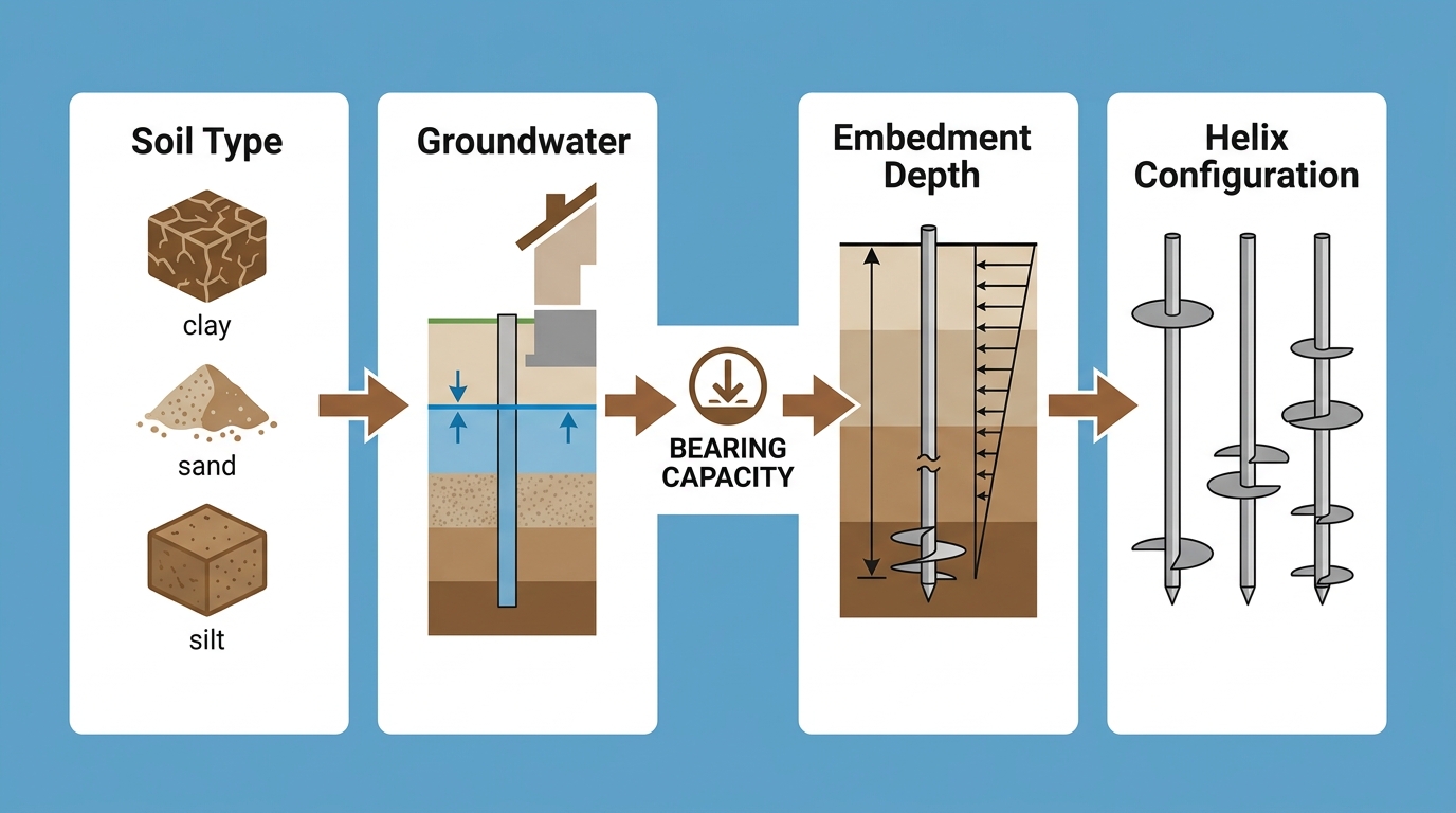
Key geotechnical factors for helical pier design and bearing capacity analysis.
With these geotechnical insights, engineers can proceed to detailed helical pier design and load calculations. The numbers on the comparison table become meaningful only when they are interpreted through the lens of site-specific subsurface data, verified by a qualified geotechnical engineer. Let us help you get your project started.
Practical Determination of Soil Bearing Capacity for Helical Pier Installation
While theoretical capacity calculations are essential, practical field methods provide the real-world verification needed for design-build projects. When evaluating soil bearing capacity for helical piers during installation, two primary methods are used: torque correlation, which offers rapid empirical estimates, and full-scale load testing, which delivers direct, high-reliability measurements. At ACN Construction, we integrate both approaches in our design-build workflow to balance cost efficiency with the confidence that every pier meets its design load.
Selecting the right verification method depends on project criticality, soil variability, and budget. The following table summarizes the key trade-offs between the two approaches.
| Soil Type | Typical Bearing Capacity Range (psf) | Effect of Water Table | Torque Correlation Quality |
|---|---|---|---|
| Clay | 1000–6000 | Significant reduction with saturation | Moderate – depends on consistency |
| Sand | 2000–8000 | Less effect but may cause liquefaction | Good – generally reliable |
| Silt | 1000–5000 | Moderate reduction; drainage matters | Fair – less consistent than sand |
Torque correlation provides a quick, low-cost estimate that works well for preliminary screening and low-risk installations, while load testing offers the highest reliability for critical structures. Understanding these trade-offs sets the stage for a deeper look at how each method is applied in practice.
Using Installation Torque to Estimate Bearing Capacity
During installation, the hydraulic drive head continuously records torque as a helical pier advances into the ground. The empirical torque correlation method converts that real-time measurement into an estimate of ultimate bearing capacity using the relationship Q_ult = Kt × T. The torque factor Kt typically ranges from 0.033 to 0.10 m⁻¹ depending on soil type; for example, we use approximately 0.075 m⁻¹ for clay and 0.055 m⁻¹ for sand in the Colorado Front Range. This approach provides a reliable estimate within ±25% for homogeneous soils, though it is not a substitute for load testing where building codes require direct verification.
When you need a quick evaluation of soil bearing capacity for helical piers, torque monitoring offers immediate feedback without delaying construction. Our installers watch torque indicators in real time, and a sudden increase often signals that the helix has reached competent bearing strata. ACN Construction documents torque readings for every pier, creating a permanent quality control record. However, because the empirical factor varies with stratigraphy, we caution that torque correlation alone is not acceptable for building code compliance evaluation in all jurisdictions; for high-load designs or expansive Front Range clays, we strongly recommend supplemental load testing.
Calculating Ultimate Geotechnical Capacity from Field Data
Engineers refine torque-based estimates by incorporating helix geometry and site-specific bearing capacity factors. A more rigorous equation takes the form:
Q_ult = σ_v′ × N_q × A_helix + c × N_c × A_helix + 0.5 × γ × B × N_γ × A_helix
Here σ_v′ is the effective vertical stress, c is cohesion, γ is unit weight, B is helix diameter, and N_q, N_c, N_γ are bearing capacity factors. In field practice, we often start with the torque reading and then back-calculate using helix area. For example, if the installation torque T is 12,000 ft-lb and we select Kt = 0.075 m⁻¹ for a clay profile, the estimated ultimate capacity Q_ult is 0.075 × 12,000 = 900 ft-lb. To express that as a bearing pressure, divide by the projected helix area A_helix. At ACN Construction, we pair this step-by-step calculation with local experience to catch anomalies before installation proceeds.
Verification Through Load Testing and Analysis
Torque correlation offers speed, but when soil conditions are highly variable or a project demands maximum certainty, we turn to axial compression and tension load tests. Load testing costs roughly $3,000–$8,000 per test and can require 4 to 48 hours, yet it produces direct measurements that are often required for building code compliance evaluation for structures requiring high reliability. Our team interprets load-settlement curves using the Davisson offset method or the 5% footing width rule to determine the failure load, then compares that value with the design load to confirm an adequate factor of safety.
In Colorado’s variable Front Range soils, load testing is strongly recommended for high-load designs or where expansive clays are present. The resulting curves not only validate capacity but also reveal stiffness and settlement behavior that helps calibrate our design assumptions. Once capacity is determined, the next step is translating these values into installation specifications for torque and depth. Let’s examine how ACN Construction applies these data during installation.
Estimates are preliminary and subject to change after site inspection and a full scope review. Please consult a licensed contractor for definitive advice; verify licensure with the Colorado Department of Regulatory Agencies (DORA).
Advanced Analysis: Calculating Ultimate Geotechnical Capacity of Helical Piles
Now that we understand what helical piles are, we can explore the advanced methods engineers use to calculate their ultimate load capacity. When analyzing soil bearing capacity for helical piers, two calculation methods dominate field practice: the bearing capacity equation approach and the installation torque correlation method. Both require careful interpretation of site-specific soil parameters, and neither can substitute for field verification.
The ultimate geotechnical capacity (Qu) of a helical pile is typically expressed as the sum of bearing resistance on each helical plate plus shaft friction. According to ACN Construction’s technical resources, the general form is Qu = (An·(c·Nc + q·Nq + 0.5·γ·B·Nγ)) + shaft resistance, where An represents the area of each helical plate, c is soil cohesion, q is the overburden pressure at plate depth, γ is the soil unit weight, and B is the plate diameter. The bearing capacity factors Nc, Nq, and Nγ must be adjusted for helical plate geometry and deep foundation conditions—commonly using Meyerhof, Hansen, or Vesic methods—rather than the shallow foundation values found in basic references. The International Building Code references these established methods for deep foundation design, and our in-house FAQ on helical pile design emphasizes that the Modified Meyerhof method is frequently used to account for the cylindrical shear failure mechanism unique to multi-helix piles.
Individual plate geometry factors significantly influence capacity. Unlike a shallow footing that mobilizes a single failure surface, each helical plate develops its own bearing zone, and spacing between helices must be sufficient—typically three diameters or more—to prevent overlapping stress bulbs. Soil shear strength parameters—cohesion for clays and friction angle for sands—directly enter the Nc and Nq factors, meaning that accurate soil boring data from a site like a residential lot in Centennial is essential to meaningful calculations. The bearing capacity of helical piles can vary widely depending on soil conditions and pile configuration, reinforcing why no single capacity number applies universally.
The torque correlation method provides a practical field check: Qu = Kt·T, where Kt is an empirical factor typically ranging from 3 to 10 for helical piles and T is the final installation torque. Kt varies with pile shaft diameter, soil type, and installation method, making it a site-calibrated parameter rather than a universal constant. Torque monitoring during installation offers real-time feedback, and engineers often compare the torque-derived capacity against the bearing capacity calculation as a consistency check. All capacity calculations remain preliminary design estimates; actual capacity must be verified by site-specific soil testing and torque monitoring during installation.
These calculations serve as a starting point; final design relies on field verification. Allowable capacity must include a factor of safety, typically 2.0 to 3.0, as required by local codes and geotechnical recommendations. With the theoretical capacity in hand, the next step is verifying performance through torque monitoring and load testing. Let us help you get your project started.
Frequently Asked Questions About Helical Pier Bearing Capacity
Now let’s address some common questions we receive about helical pier bearing capacity and the factors that influence how much weight these foundation systems can safely support.
What affects helical pier bearing capacity?
The soil bearing capacity for helical piers depends primarily on soil type, pier diameter, and installation depth. In the Denver area, expansive clay soils, sandy loam, and rocky substrates each present different load-bearing characteristics. We assess soil conditions through site-specific investigation because theoretical capacity alone cannot account for real-world variability.
What are typical bearing capacities for residential projects in Colorado?
For residential foundations in our local Centennial and Denver service area, helical pier capacities typically range from 30 to 100 kips per pier depending on soil composition and pier configuration. However, every project is unique, and capacity estimates require a site-specific evaluation before design decisions are finalized.
How does ACN Construction determine design capacity?
Our process for determining design capacity begins with a thorough site inspection, followed by soil borings or torque correlation to establish soil parameters, and concludes with engineering review. We emphasize that no single capacity number fits all situations, and we combine theoretical planning with rigorous field verification.
Do you perform load testing to verify capacity?
Yes, we use both torque correlation during installation and compression or tension load tests when project conditions warrant field verification. As documented in our published FAQ content, theoretical load capacity and actual load testing can differ due to soil disturbances and inherent variability during installation. This validation ensures your foundation meets all safety and structural codes.
For a project-specific evaluation, Request a Quote or Call Us 24/7. Let us help you get your project started.
Disclaimer: Capacity depends on site-specific conditions and should be evaluated by a licensed engineer. Project outcomes and timelines may vary based on site conditions, material availability, and unforeseen issues.
Ensuring Foundation Safety with Proper Helical Pier Design
To ensure foundation safety, proper helical pier design must account for site-specific soil bearing capacity for helical piers. ACN Construction evaluates geotechnical soil reports, structural loads, frost depth, and local building codes to determine the correct pier size, helix diameter, and embedment depth. This data-driven process places each pier below expansive clay layers common in Centennial into stable load-bearing strata, helping to prevent differential settlement—a leading cause of foundation cracks and long-term structural failure. Because soil bearing capacity often varies within a single lot, every pier is engineered for its precise location. With the design tailored to site conditions, installation can proceed with confidence. Let us help you get your project started—Request a Quote today.
Resources