Soil Bearing Capacity for Helical Piers: A Guide for Centennial
Table of Contents
- Soil Bearing Capacity for Helical Piers in Centennial, Colorado
- Fundamentals of Soil Bearing Capacity for Helical Pier Foundations
- Deep Dive: Geotechnical Factors That Influence Helical Pier Bearing Capacity
- Practical Determination of Soil Bearing Capacity for Helical Pier Installation
- Advanced Analysis: Calculating Ultimate Geotechnical Capacity of Helical Piles
- Frequently Asked Questions About Helical Pier Bearing Capacity
- Ensuring Foundation Safety with Proper Helical Pier Design
Soil Bearing Capacity for Helical Piers in Centennial, Colorado
Understanding Soil Bearing Capacity for Helical Piers
The performance of any helical pier depends on the soil beneath it—which brings us to soil bearing capacity for helical piers. Simply put, soil bearing capacity is the maximum load the ground can support without excessive settlement or shear failure. When we install helical piers for clients in Centennial, CO and the Denver metro area, this property directly determines how deep the piers must go and what configuration is needed.
Several key soil properties influence ground bearing capacity. Soil type is the starting point—cohesive clays behave very differently from granular sands or gravels under load. Density and compaction dictate how tightly particles are packed, while moisture content can dramatically alter soil strength, especially in Colorado’s expansive clay formations. The depth of the bearing stratum is equally critical: helical piers function by transferring structural loads past weak surface soils down to competent, load-bearing layers. That is why understanding subsurface support capacity at the pier termination depth matters far more than surface conditions.
Our engineers use precise helical pier load capacity calculations, which directly incorporate soil bearing capacity data gathered from geotechnical reports. ACN Construction’s internal estimator guides offer typical soil bearing ranges for common Colorado soil types, providing a useful preliminary reference point. However, all load estimates are preliminary and must be validated by a site inspection and geotechnical analysis. Factors like lateral loads, frost depth, and corrosion potential also influence final pier design, but soil strength for helical piers remains the foundation of every calculation.
With a solid grasp of soil bearing capacity, we can move on to how these numbers feed into actual load capacity determinations—a step where precision makes all the difference.
Key Concepts of Soil Bearing Capacity for Helical Piers
Before we explore installation methods, it is important to understand the soil bearing capacity concepts that govern helical pier performance. Understanding soil bearing capacity for helical piers is fundamental to designing reliable foundations that will support structures safely for decades. At its core, soil bearing capacity refers to the maximum pressure the ground can support before it fails under loading. For helical pier applications, this capacity determines everything from pier depth and diameter to the number of helix plates required for adequate support.
When we assess bearing capacity for helical piers, we distinguish between two critical measurements: ultimate bearing capacity and allowable bearing capacity. The ultimate bearing capacity represents the maximum pressure the soil can support before failure occurs—the point at which the ground physically gives way beneath the applied load. However, engineers never design foundations to this limit. Instead, they apply a safety factor, typically ranging from 2 to 3, to derive the allowable bearing capacity. According to ACN Construction’s internal design guidance, this safety margin ensures that the foundation can withstand loads significantly higher than the projected minimum requirements, accounting for variables like construction tolerances, soil variability, and unexpected loading conditions.
Helical piers gain their load-bearing capability through two primary mechanisms: end bearing on the helix plate or plates, and skin friction along the steel shaft. The dominant mechanism depends heavily on the soil capacity for helical pier foundations at a given site. In dense, granular soils like compacted sand, end bearing provides the majority of the resistance as the helix plates press against firm strata. In cohesive clay soils, however, skin friction along the shaft often contributes a substantial portion of the total capacity. The bearing capacity of soil in helical pier design therefore depends on understanding which load transfer mechanism will prevail at the installation depth.
To quantify these behaviors, geotechnical engineers use the Mohr-Coulomb failure criterion, which describes soil strength through two key parameters: cohesion (c) and the internal friction angle (φ). Cohesion represents the electrochemical bonding between fine soil particles and dominates the behavior of clays, which can stand vertically when excavated due to this inherent stickiness. The friction angle, by contrast, governs the strength of granular soils like sands and gravels, where particles interlock and resist movement through mechanical friction rather than chemical bonds. In practical terms, cohesion values are high for stiff clays but zero for clean sands, while friction angles range from nearly zero in saturated soft clays to 45 degrees or more in dense, well-graded sands.
The table below summarizes typical bearing capacity ranges for common soil types encountered in the Denver metro area, along with their cohesion values, friction angles, and the reliability of using installation torque to estimate capacity.
| Soil Type | Typical Bearing Capacity Range (psf) | Effect of Water Table | Torque Correlation Quality |
|---|---|---|---|
| Clay | 1000–6000 | Significant reduction with saturation | Moderate – depends on consistency |
| Sand | 2000–8000 | Less effect but may cause liquefaction | Good – generally reliable |
| Silt | 1000–5000 | Moderate reduction; drainage matters | Fair – less consistent than sand |
Dense sand offers the highest bearing capacities in this comparison because, although it has zero cohesion, its high friction angle creates substantial interlocking resistance under load. This soil type also exhibits the most reliable torque correlation during installation, meaning the rotational force required to advance the pier closely correlates with the ultimate capacity achieved. Stiff clay also provides excellent bearing capacity, typically 3,000 to 5,000 pounds per square foot, but its torque correlation reliability is only moderate because of the complex way cohesive soils respond to displacement during helical pile installation.
At the lower end of the spectrum, loose sand and soft clay present greater challenges for helical pier design. Loose sand, with friction angles between 28 and 34 degrees, can densify and settle under load, producing less predictable torque-to-capacity relationships. Soft clay, with bearing capacities as low as 500 pounds per square foot, requires careful engineering evaluation because its low cohesion and negligible friction angle make torque correlation unreliable. In these conditions, we typically recommend deeper pier embedment to reach more competent strata rather than relying on surface-level soil properties.
The torque correlation method itself uses an empirical factor Kt to convert installation torque into an estimate of ultimate capacity. For a single-helix pier, a typical Kt value is 10 ft⁻¹, though this factor varies by soil type and pier configuration. The method is most reliable in granular soils where the relationship between torque and bearing capacity is well established, moderately reliable in stiff cohesive soils, and least reliable in soft clays where pore water pressure effects can produce misleading torque readings. This variability underscores why site-specific geotechnical data is essential for accurate pier design.
It is important to note that the values presented in the table are approximate ranges based on typical soil mechanics data and helical pier industry practice. Actual bearing capacity at any specific site can vary substantially and must be verified through a comprehensive geotechnical investigation and, where required by the project scope, load testing. ACN Construction always recommends that a licensed geotechnical engineer assess site conditions before finalizing any helical pier foundation design. With a grasp of these soil capacity fundamentals, you can better appreciate the installation torque monitoring we perform on every project.
Engineering Principles Behind Helical Pier Capacity
To design a helical pier foundation, engineers rely on established principles of soil mechanics and proven measurement techniques. In our Centennial practice, we combine theoretical geotechnical knowledge with field verification methods to ensure every pier installation meets the required structural performance. Understanding soil bearing capacity for helical piers involves examining how the ground resists applied loads and how we can predict that resistance before construction begins. Three complementary approaches—soil mechanics theory, empirical torque correlation, and field load testing—form the backbone of modern helical pier capacity determination.
Soil Mechanics and Bearing Capacity Theory
Understanding soil bearing capacity for helical piers begins with soil mechanics fundamentals. The concept of effective stress governs how granular soils like sands and gravels transfer load. In these cohesionless materials, the soil skeleton—not pore water—carries structural forces through particle-to-particle contact. When we install a helical pier into dense sand, the interlocking grains create frictional resistance that supports the helix plates. In contrast, cohesive soils such as clays derive their strength from electrochemical bonds between fine particles, and their capacity depends on undrained shear strength rather than friction angle alone. A thorough geotechnical investigation must provide soil parameters including friction angle, cohesion, and unit weight before we can perform theoretical calculations for any helical pier design.
Bearing capacity failure mechanisms fall into three categories: general shear, local shear, and punching shear. In general shear failure, a well-defined slip surface extends to the ground surface, accompanied by sudden settlement. Local shear failure shows partial rupture zones beneath the foundation without surface heave. For helical piers specifically, failures typically involve punching shear in granular soils, where the pier compresses the soil directly beneath the helix plates without developing extensive shear planes. This mechanism explains why deeper installations into competent bearing strata so dramatically improve performance. We consider these soil behaviors when determining pier depth, helix configuration, and spacing requirements for projects throughout the Centennial area and the broader Denver metro region.
Torque Correlation for Capacity Estimation
The torque correlation method provides a practical field tool for estimating helical pier load capacity calculations. The fundamental equation relates installation torque directly to axial capacity: Q = Kt × T, where Q represents ultimate capacity, T measures installation torque, and Kt serves as the empirical torque correlation factor. This factor typically ranges from 0.02 to 0.25 ft⁻¹ depending on soil type and helix geometry. According to our engineering team at ACN Construction, Kt values must be calibrated to specific site conditions because soil variability significantly influences the torque-to-capacity relationship. Without site-specific calibration, the torque correlation method achieves moderate accuracy, typically within 15 to 30 percent of actual capacity—sufficient for rapid field verification during installation but not a substitute for rigorous soil investigation.
The advantages of torque correlation include speed and cost-effectiveness relative to full-scale load testing. During installation, we monitor torque continuously and can make immediate decisions about pier depth or helix configuration. However, limitations exist. The method remains sensitive to soil layering, installation rate, and helix geometry. Different soil types produce different torque signatures for the same ultimate capacity, meaning a single Kt factor cannot apply across varied ground conditions without adjustment. We recommend calibrating torque correlation through selected load tests whenever project conditions permit, particularly for critical structures or sites with known soil variability. For projects in our Centennial service area, where subsurface conditions can transition between expansive clay and granular deposits over short distances, this calibration step proves essential for reliable capacity estimation.
Load Testing: The Ultimate Verification
Field load testing represents the most reliable method for verifying helical pier bearing capacity. Standard procedures follow ASTM D1143 for compression loading and ASTM D3689 for tension loading. These tests apply incremental load steps to an installed test pier while measuring settlement at each increment. Our team conducts tests by loading the pier in stages, typically at 5 to 10 percent of the anticipated failure load, and holding each increment until the rate of settlement meets established criteria. This approach generates load-settlement curves that reveal the pier’s actual behavior under service and ultimate loading conditions.
Interpreting load-settlement curves requires established failure criteria. The Davisson offset method remains widely accepted for determining the interpreted failure load from test data. This method defines failure at the load corresponding to a settlement equal to elastic compression plus a specified offset, typically 0.15 inches plus pier diameter divided by 120. Test results can then refine torque correlation factors or validate theoretical bearing capacity calculations performed during the design phase. Load testing yields high accuracy, typically within 5 to 10 percent of true ultimate capacity. However, the testing process involves significant time and equipment cost, which limits its application to a representative number of test piers rather than production pier verification. We use load test results to calibrate our installation parameters, ensuring production piers installed to consistent torque values achieve the required design capacity across the entire project site.
Comparing Capacity Determination Methods
Selecting the appropriate capacity determination method depends on project requirements, site conditions, and the level of certainty needed. The following table summarizes the three primary approaches we consider for helical pier design projects:
| Method | Reliability | Cost | Time Required | Applicability to Soil Types |
|---|---|---|---|---|
| Torque Correlation | Moderate – derived empirical relationships | Low | Minutes | Best for sand and clay |
| Load Testing | High – direct measurement | High | Hours to days | All soil types |
This comparison demonstrates why we integrate multiple methods rather than relying on any single approach. Theoretical bearing capacity equations guide initial design, torque correlation provides real-time installation feedback, and selective load testing confirms that performance meets expectations. For projects in our Centennial and Denver metro service areas, this multi-layered verification strategy accounts for the variable soil conditions and ensures foundation performance meets structural requirements.
The chosen capacity determination method directly informs both design decisions and installation oversight. By understanding how soil mechanics, torque measurement, and load testing work together, property owners and engineers can make informed choices about foundation repair and new construction projects that demand reliable deep foundation support.
Practical Steps to Determine Soil Bearing Capacity for Installation
With the theoretical background established, the following steps outline how to practically determine bearing capacity for a specific site. Determining soil bearing capacity for helical piers is essential for safe design, as the entire foundation system relies on the soil’s ability to support structural loads without excessive settlement or failure. A systematic approach combines subsurface investigation, real-time field measurements, and engineering interpretation to arrive at a reliable configuration.
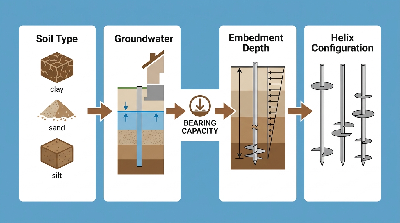
Key geotechnical factors for helical pier design and bearing capacity analysis.
Three-step process to determine soil bearing capacity for construction.
By following a structured methodology, installers can identify suitable bearing strata and confirm that each pier meets its design load. This process reduces the risk of unforeseen subsurface conditions compromising foundation performance.
Conducting a Geotechnical Investigation
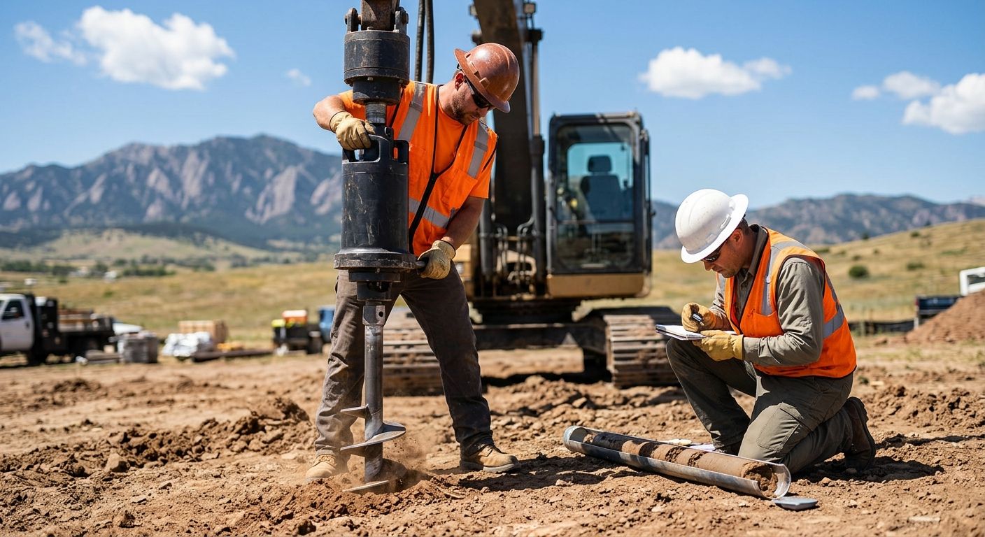
A thorough geotechnical investigation remains the foundational step for evaluating soil bearing capacity for helical piers. The typical scope includes soil borings advanced to a depth of at least 1.5 times the anticipated pier embedment, capturing samples at regular intervals and whenever the material changes. Standard penetration tests or cone penetration test soundings provide continuous or semi-continuous profiles of soil resistance, helping delineate weak layers from competent bearing strata.
Laboratory testing on recovered samples quantifies engineering properties that control pier behavior. Moisture content and Atterberg limits classify fine-grained soils, while direct shear or triaxial compression tests measure drained friction angle and cohesion intercept. According to ACN Construction’s load capacity guidance, these strength parameters combined with layer thicknesses form the basis for calculating ultimate bearing capacity. The geotechnical report deliverables should present a detailed soil profile with layer descriptions, groundwater observations, recommended strength values, and preliminary bearing capacity estimates for the depths under consideration.
Field Torque Measurement Protocols
Once the subsurface profile is understood, field torque measurement provides real-time verification during helical pier installation. Installers use a torque transducer or a calibrated hydraulic motor mounted on the drive head to record installation torque at each helix advancement, typically every one to two feet of penetration. Maintaining a consistent rotation speed between 5 and 20 revolutions per minute helps ensure that recorded values reflect actual soil resistance rather than speed-induced anomalies.
The torque-capacity correlation converts field readings into an estimated ultimate capacity through the relationship Q = Kt × T, where Q is ultimate capacity, T is installation torque, and Kt is an empirical factor. For helical piers in compression, Kt typically ranges from 0.10 to 0.25, though site-specific calibration through load testing improves accuracy. ACN Construction notes that the torque correlation method serves as the primary tool for real-time verification on their projects, with torque indicators allowing crews to monitor depth, penetration rate, and potential soil anomalies continuously. This approach proves more reliable in granular soils than in cohesive clays, where pore pressure effects can temporarily reduce measured torque.
Interpreting Soil Bearing Capacity Results
With geotechnical data and torque records in hand, the team can interpret soil bearing capacity for helical piers and select an appropriate configuration. The process begins by comparing the ultimate bearing capacity whether derived from the geotechnical report or field torque data to the required design load. Industry standards such as ICC-ES AC358 recommend applying a safety factor, typically between 2.0 and 3.0, to the ultimate capacity to arrive at an allowable working load.
When bearing capacity falls below expectations, the helical pier configuration can be adjusted. Options include increasing helix diameter, adding additional helix plates on the shaft, or extending embedment depth to reach a denser stratum. For detailed guidance on helical pier load capacity calculations, refer to our dedicated resource that walks through the torque-capacity method step by step.
The following table summarizes common field test methods used to verify soil bearing capacity for helical piers.
| Test Type | Primary Data | Precision |
|---|---|---|
| SPT | Blow counts | Standard |
| CPT | Tip resistance | High |
Both SPT and CPT remain the most common investigation methods for helical pier design. Plate load tests are not standard for deep foundations, and ICC-ES AC358 emphasizes torque correlation or full-scale load testing as the preferred acceptance path. Every result must be documented in a field report that captures torque readings at each interval, soil strata encountered, final embedment depth, and the corresponding capacity estimate. This documentation package provides the engineering record required for approval and stands as a permanent quality control reference for each installed pier. Once the soil bearing capacity is determined and the helical pier configuration selected, the installation process can proceed as described in the next section.
Advanced Factors in Helical Pier Bearing Capacity Analysis
When analyzing soil bearing capacity for helical piers, several advanced factors come into play that go beyond simple soil classification. As a design-build team, we know that these factors directly influence the pier configuration, installation depth, and the confidence we have in the final foundation support. The bearing capacity of helical piers is not a fixed value; it emerges from the interaction between the pier geometry, the subsurface soil profile, and the installation process itself. A thorough helical pier capacity analysis considers torque, helix design, soil layering, and groundwater conditions before arriving at a site-specific solution.
One of the most practical tools in the field is the torque correlation factor, or Kt. This factor converts the torque measured during installation into an estimated ultimate pier capacity. Based on our design and installation experience, Kt typically ranges from 3 to 20, depending on the soil type and the configuration of the helices. Sandy soils often produce lower Kt values, while stiff clays yield higher numbers, and our team references standard industry tables alongside our own project records to select an appropriate Kt for each project.
Helix geometry plays an equally important role among factors affecting pier bearing capacity. Larger-diameter helices increase the bearing area and can support greater loads, but they also require higher installation torque. To avoid interference between adjacent helices, we follow the spacing guideline of at least three times the helix diameter, a recommendation documented in our installation FAQ. This spacing ensures each helix contributes independently to the pile capacity without overlapping stress zones.
Soil stratification adds another layer of complexity. When a pier penetrates multiple soil layers, the contribution from each helix must be evaluated according to the soil type at its specific depth. The torque profile recorded during installation serves as a real-time indicator of changing soil strength, helping us confirm whether the helices have reached a competent bearing stratum. In cohesive soils, shaft adhesion contributes meaningfully to total capacity; in granular soils, end bearing on the helices typically dominates. An advanced helical pier capacity analysis therefore accounts for both the end-bearing resistance and the friction along the shaft.
Groundwater can significantly influence these calculations. Saturated soils experience reduced effective stress, which can lower both end-bearing resistance and shaft friction. Installation below the water table may also cause temporary soil disturbance, and we apply appropriate correction factors when groundwater is present to ensure our capacity estimates remain conservative.
Ultimately, the most reliable method to verify design assumptions is field torque monitoring during installation. Our team at ACN Construction uses continuous torque readings to confirm that the pier achieves the required capacity in the actual site conditions. While these advanced factors refine the analysis, final bearing capacity must be verified on a site-specific basis by a licensed engineer.
Disclaimer: The information provided here is educational in nature. Estimates are preliminary and subject to change after a site inspection and a full scope review. Project outcomes may vary based on site conditions, and all designs must be confirmed by a qualified engineer.
Frequently Asked Questions About Soil Bearing Capacity for Helical Piers
You may have some questions about how soil conditions affect helical pier installation for your project. Here are answers to common inquiries we receive in Centennial and across our Colorado service areas.
What is soil bearing capacity for helical piers?
Soil bearing capacity for helical piers is the load the ground can safely support without excessive settlement. It determines how deep we must install piers to reach stable, load-bearing strata.
How do we determine the bearing capacity of the soil for helical pier foundations in Centennial?
As part of our design-build process, we perform a site-specific evaluation. Soil profiles vary significantly, and locally expansive clay soils often require deeper installations to achieve the required load-bearing capacity of the soil.
How is capacity verified during installation?
We use torque monitoring during installation, which provides real-time confirmation that each pier has reached a competent soil layer with sufficient strength for the structural load.
For a project-specific assessment, Request a Quote after a site inspection. Let us help you get your project started.
Disclaimer: Project outcomes may vary based on site conditions; consult a licensed contractor for definitive advice.
Partnering with Experts for Reliable Helical Pier Foundations
Of course, achieving those results depends on working with the right partner. Partnering with experts ensures accurate soil bearing capacity for helical piers—without it, even the best materials fall short. Our design-build model provides single-point accountability, from engineering through installation, so your project never gets lost between separate firms. We combine that accountability with deep local knowledge of Centennial and Denver-area soil types and permitting timelines. Our team’s familiarity with local building code compliance evaluation ensures every helical pier meets jurisdiction requirements. Because ground-support evaluation is site-specific, we always conduct a full inspection before providing an estimate—estimates are preliminary and subject to change after site inspection and full scope review. Let us help you get your project started.
Resources